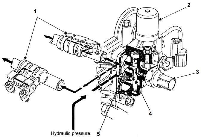
NOTE:
Follow the instructions of each troubleshooting for specific inspection points and measurement conditions.
Open Wire Inspection
Inspection Method by Resistance Measurement
Continuity Check
- Disconnect the connector on each component that includes the circuit you are inspecting.
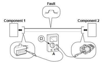
2.Measure the resistance (A) of the wire, connector to connector.
Normal Condition: Less than 1 Ω (continuity)
Inspection Method by Voltage Measurement
Voltage Difference Check
NOTE:
In this example, a circuit can be checked for an open by measuring the voltage if one end of the circuit is connected to a power supply or reference voltage.
- Disconnect the connector (A) of the component receiving the power supply or reference voltage.
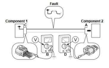
2.Measure the voltage (B) at the connector terminal (C) outputting the power supply or reference voltage to body ground.
3.Measure the voltage (D) at the connector terminal (A) of the component receiving the power supply or reference voltage.
Normal Condition: Voltage (B)=Voltage (D)
Abnormal Condition (Open Circuit): Voltage (B)>Voltage (D)
Shorted Wire Inspection (Short to Power Supply)
Inspection Method by Resistance Measurement
Continuity Check
- Disconnect the connector on each component that is part of the circuit you are inspecting.
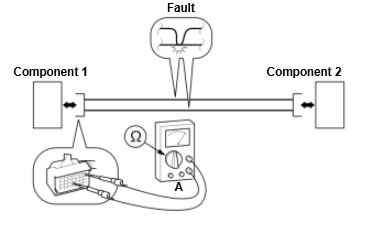
2.Measure the resistance (A) between the connector terminal you are inspecting to other power lines within the same connector.
Normal Condition: More than 1 MΩ (no continuity)
Inspection Method by Voltage Measurement
Voltage Check
NOTE:
A short to power can be checked by measuring the circuit presumed to be normal at 0 V.
- Disconnect the connector on each component that is part of the circuit you are inspecting.
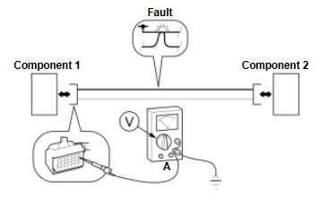
2.Measure the voltage (A) to body ground at either end of the circuit.
NOTE:
Voltage checks should be done in different vehicle modes (ON, OFF, ACC, etc.).
Normal Condition: 0 V
Shorted Wire Inspection (Short to Ground)
Inspection Method by Resistance Measurement
Continuity Check
- Disconnect the connector on each component that is part of the circuit you are inspecting.
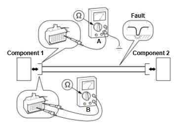
2.Measure the resistance (A) between the connector terminal you are inspecting to body ground.
Normal Condition: More than 1 MΩ (no continuity)
3.Measure the resistance (B) between the connector terminal you are inspecting to other GND lines within the same connector.
Normal Condition: More than 1 MΩ (no continuity)
Inspection Method by Voltage Measurement
Voltage Check
NOTE:
A short to body ground can be checked by measuring the circuit presumed to be normal with either battery or reference voltage.
- Disconnect the connector (A) of the component receiving the power supply or reference voltage.
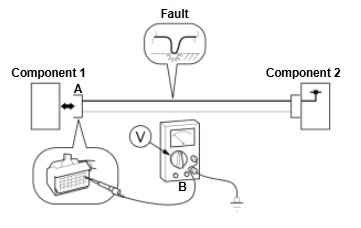
2.Measure the voltage (B) at the connector terminal (A) receiving the power supply or reference voltage to body ground.
NOTE:
Voltage checks should be done in different vehicle modes (ON, OFF, ACC, etc.).
Normal Condition: Power supply or reference voltage