Automatic Transmission Overview
When driving a vehicle, the driver operates the steering wheel, the gearshift lever, the
accelerator pedal, the clutch pedal, the brake pedal and other similar controllers in response
to the condition of the road and to the type of driving which is being performed. In this, the
clutch pedal and the gearshift lever are required to be operated with great frequency, placing
a considerable burden on the vehicle’s driver. Devised as a means of reducing this burden,
the automatic transmission (or AT) allows the vehicle to automatically perform gearshift
operations in response to load, speed, and other relevant conditions.
Automatic Transmission Basic Construction
The principle components of an automatic transmission are the torque converter, the gear
unit, and the hydraulic control unit.
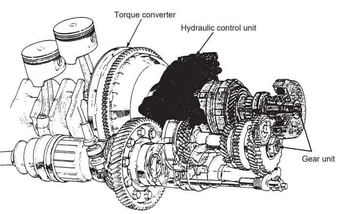
The function of the torque converter mechanism is to transfer the engine’s output power to
the gear unit through the action of a special fluid. However, it also operates in the complete
reverse also. Consider an example where the vehicle is stopped — it will be important for
the torque converter’s fluid to absorb any variations in speed and to “not transfer” engine
power in such a situation.
Furthermore, the torque converter has another important role to fulfil in the operation of the
vehicle; specifically, it must function to increase the engine torque in a set output range.
However, it will not be possible to deal adequately with all possible situations using torque
increases generated by the torque converter alone, and for this reason, further changes to
the driving force are made to the gear unit in accordance with the current driving condition.
In addition, the gear unit is also called upon to implement the necessary gear changes when
the vehicle is to be driven in reverse.
The hydraulic control unit converts engine load, speed, and other similar variables into
hydraulic signals and controls the shifting of the gear unit in accordance with the
corresponding hydraulic pressures. This component also performs control of the lock-up
clutch, which will be discussed later in this article.
Automatic Transmission Torque Converter
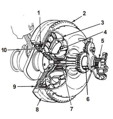
The torque converter is mounted to the crankshaft via the drive plates and operates as a
flywheel, using its mass to stabilize the rotation of the engine. A starter ring gear is fitted to
the outside of the converter for use by the starter.
- Lock-up clutch
- Starter ring gear
- Pump
- Stator
- Transmission main shaft
- Stator shaft
- One-way clutch
- Torque converter cover
- Drive plate
- Turbine
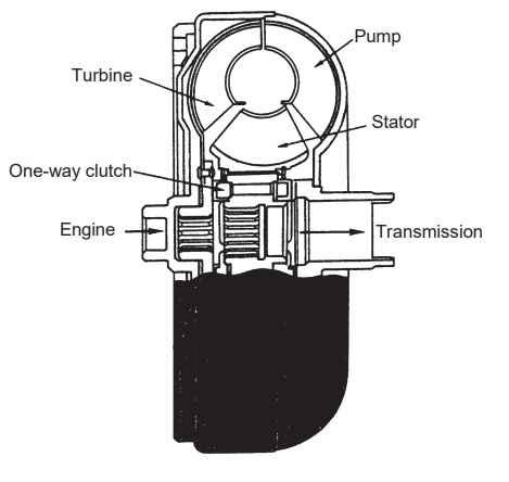
The torque converter is a type of fluid coupling. Accordingly, it performs the transfer of
torque through the action of the fluid which it contains.
Fluid Coupling
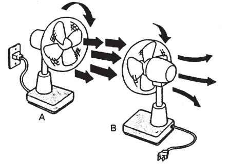
Let’s look briefly at the operation principle of a fluid coupling and consider a situation as
shown in the diagram where two fans are positioned facing each other. If fan A is operated
to produce a flow of air (or, in other words, to force air to move), this air will be directed at the
vanes of fan B, causing it to rotate also. A fluid coupling performs the transfer of torque in a
fashion which is similar to this transfer of motion by the fans.
Referring again to the example in the above diagram, the flow of air that passes through fan
B still possesses a considerable amount of energy. And if ducts are used to redirect this air
flow to the rear of the vanes in fan A, then the rotation of that fan will be assisted and torque
will be subsequently increased. It is this principle upon which the operation of a torque
converter is based.
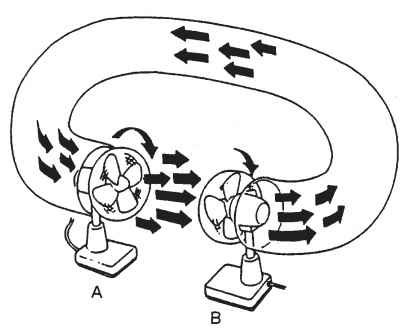 If we compare the above example with the condition of an actual torque converter, we can
see that the pump fills the role of fan A, the turbine fills the role of fan B, and the stator fills
the role of the ducting.
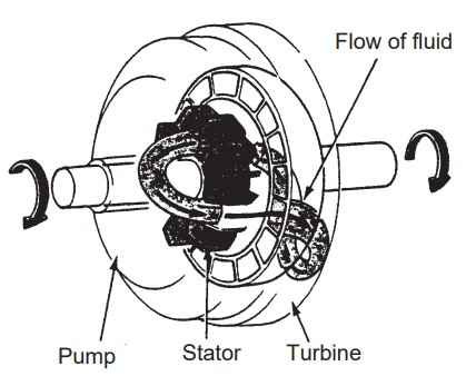 Torque Converter
This section will describe the flow of fluid in an actual torque converter.
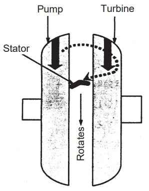
The flow of fluid which is created due to operation of the pump is directed at the vanes of the
turbine and rotates the turbine. The fluid then flows along these vanes and leaves the turbine. A reaction force will be generated as a result of the outflow of fluid, and this force also makes the turbine to rotate.
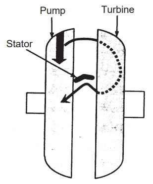
The fluid which has left the turbine is guided back to the rear of the pump’s vanes by the
stator. There, it pushes against the rear of the vanes and assists the rotation of the pump.
The torque convertor employs this method as a means of increasing torque.
If the speed of the turbine should increase, then the direction of the fluid which is discharged
from this component will change accordingly. When this happens, the amount of fluid that is
redirected by the stator to accelerate the pump will decrease, thus leading to a reduction in
the torque-increase effect.
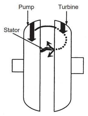
Then, if the speed of the turbine exceeds a predetermined limit, the flow which is discharged
from this component will effect the rear of the stator in such a way that it promotes reverse
rotation of the pump, thus generating larger power losses. If this should happen, the stator’s
one-way clutch will begin to operate to cause the stator to freewheel and to consequently
limit power losses. The point at which this type of operation commences is known as either
the “coupling point” or the “clutch point.” When the coupling point is exceeded, the increase
of torque is not carried out and the torque convertor operates as a simple fluid coupling.
 The following diagram presents a graph of the above-mentioned type of operation.
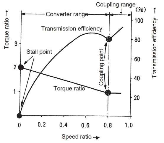 Speed ratio = Turbine speed / Pump speed
Torque ratio = Turbine axle torque / Pump axle torque
Transmission efficiency = (Output power / Input power) x 100
When the speed ratio is 0 (i.e., at what is called the “stall point”), the turbine will not be
rotating and the torque ratio will reach its maximum value of 2. The torque ratio then decreases as the speed ratio gets increasingly large, reaching a value of 1 at the coupling point. Freewheeling of the stator is implemented beyond this point to prevent against further reductions in the torque ratio. Note that, because of the mechanical and other losses which
exist in the fluid coupling, the speed ratio can never reach a value of 1 — that is to say, the pump and the turbine can never rotate at exactly the same speed.
The transmission-efficiency curve is determined by the shape of the torque converter.
Beyond the coupling point, this characteristic becomes a straight line; however, due also to
the losses which occur within the fluid coupling, the transmission efficiency cannot reach a
level of 100%.
Lock-up Mechanism
As detailed in the previous section, a torque-transmission efficiency of 100% cannot be
achieved within the torque converter. And when automatic transmission vehicles are compared with manual transmission vehicles, this factor is one of the reasons for the relatively poor fuel efficiency of the former. In order that the negative effect of this factor can be limited in some way, automatic transmission vehicles are fitted with lock-up mechanisms.
The lock-up mechanism is a hydraulically-controlled clutch. At certain, predetermined
conditions, this clutch will engage so that engine power can be transferred directly to the
transmission without using the torque converter. As a result of this action of the lock-up mechanism, a transmission efficiency of 100% can be achieved at these times.
In addition, certain models exist wherein electronic control has been implemented for the
control of the lock-up mechanism only.
Automatic Gear Unit
Generally speaking, the gear units in Honda automatic transmissions are essentially
common with those used in manual transmissions. At present, 4-speed transmissions are
most widely used.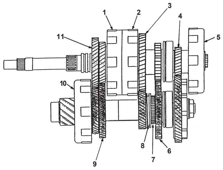
- 2nd clutch
- 4th clutch
- Mainshaft 4th gear
- Mainshaft 1st gear
- 1st clutch
- Countershaft reverse gear
- Reverse selector hub
- Reverse selector
- Countershaft 2nd gear
- 3rd clutch
- Mainshaft 3rd gear
The most fundamental difference between the gear units of automatic transmissions and of
manual transmissions is the fact that the hydraulically-controlled multiple-disc clutches are
implemented in the former instead of synchronizers. These clutches are used to connect
gears to the shafts so that gearshifts may be implemented.
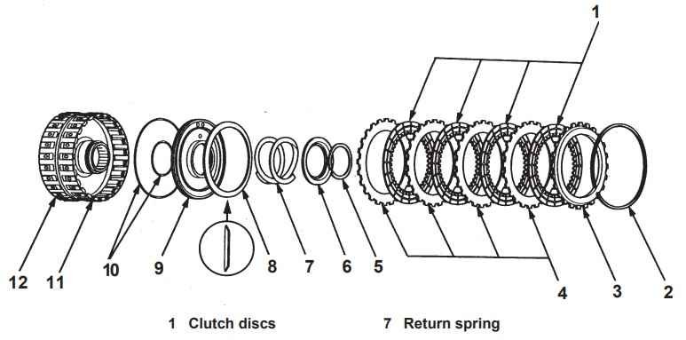
- Clutch discs
- Snap ring
- Clutch end plate
- Clutch plates
- Snap ring
- Spring retainer
- 7 Return spring
- Disc spring
- Clutch piston
- O-rings
- 4th clutch drum
- 3rd clutch drum
However, in the case of reverse gear, hydraulic pressure is used to actuate a shift fork so that
the counter shaft and counter reverse gear can be engaged.
Gearshift Mechanism
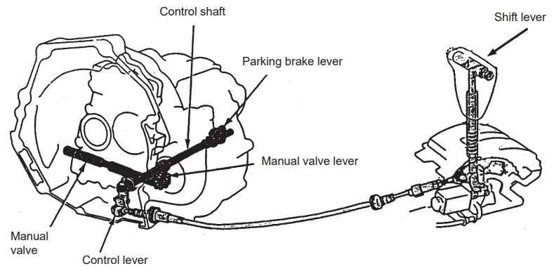
In an automatic transmission, the shifting of gears within the range selected by the driver is
performed in an automatic fashion. Specifically, the motion of the gearshift lever is directed
via a control cable to the hydraulic control unit’s manual valve. This action allows fluid passages within the control unit to be switched over so that the correct range can be selected. Note that in the D4 range, automatic selection is performed from 1st gear to 4th gear; in the D3 range, from 1st gear to 3rd gear; and in the 2 range, shifting is fixed in 2nd gear. In addition, reverse gear is selected in the R range, and the countershaft is mechanically immobilized in the P range.
Hydraulic Control Unit
Hydraulic pressure is used in a number of situations inside the automatic transmission for
the purpose of control. This hydraulic pressure is supplied by an ATF pump which is driven
by the torque converter housing’s pump drive gear.
The hydraulic control unit receives signals relating to the driver’s desired operation, the current condition of the vehicle, and other similar factors — these signals having been converted into hydraulic form. Valves inside the control unit operate in response to the hydraulic signals, switching the channels along which flow will occur. For example, by applying the pressure in the 2nd clutch channel while releasing pressure in the 1st clutch channel, it is possible to switch from 1st gear to 2nd gear smoothly. All other gear-shifting operations can be performed in a similar manner.
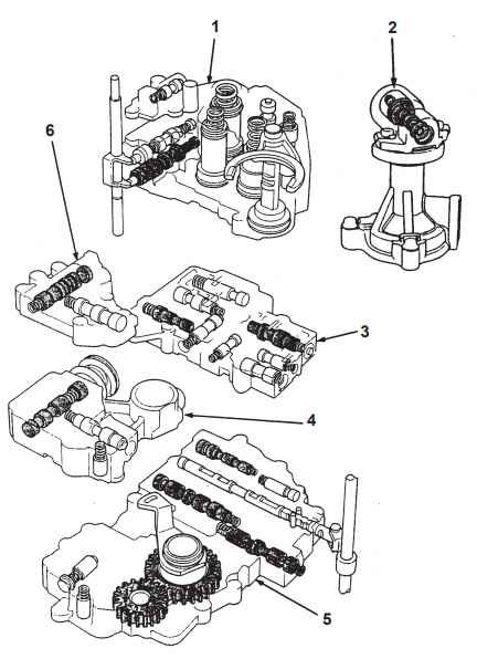
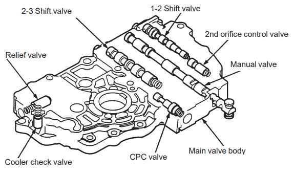
The hydraulic control unit contains the following valve bodies.
- Servo valve body
- Governor valve body
- Secondary valve body
- Regulator valve body
- Main valve body
- Lock-up valve body
- Servo valve body
- Governor valve body
- Secondary valve body
- Regulator valve body
- Main valve body
- Lock-up valve body
Differential Valve
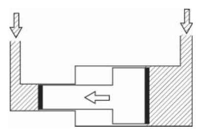
One of the most frequently used components in a hydraulic control unit is a type of valve
known as a differential valve. When hydraulic pressure is applied to a differential-type valve,
differences in the areas to which this pressure is applied will cause the valve to actuate in a
specific direction.
For example, if a uniform pressure was applied to the valve from the following diagram, the valve would move to the left due to the fact that the exposed area is greater on the right than
on the left.
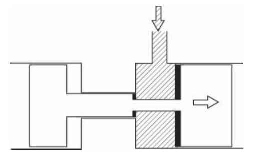
Alternatively, the valve would move to the right if the difference in areas was similar to that
shown in the following diagram.
By assembling a number of these valves together, it is possible to perform switching within
hydraulic circuits.
Shift Change Method
By these two pressures, the unit moves the shift valves to change the gear clutch to which the hydraulic pressure is applied to engage a gear.
As mentioned previously, the hydraulic control unit changes the vehicle’s gearing in response to various vehicle conditions. To do this, the hydraulic control unit uses the hydraulic pressures which represent the engine load and vehicle speed.
Detection of Engine Load
The detection of engine load is carried out using throttle valve A, which moves in synchrony
with the opening and closing of the throttle. The hydraulic pressure corresponding to the current degree of throttle opening (i.e., the throttle-A pressure) is generated.
Detection of Vehicle Speed
The governor valve regulates the line pressure in accordance with the vehicle speed, when the vehicle speed is low, the governor valve opens slightly. When the vehicle speed is high, it opens widely. In this way, the line pressure is modified to the governor pressure that represents the current vehicle speed.
Looking at the following schematic diagram, the connections between the 1-2, 2-3, and 3-4 shift
valves can be identified. Each of these valves is of a different diameter, and furthermore, the
strength of the integrated spring varies from valve to valve. Also, because the current situation
corresponds to times when the accelerator pedal is depressed, the left side of each of the valves is exposed to the throttle pressure; the right side, to the governor pressure.
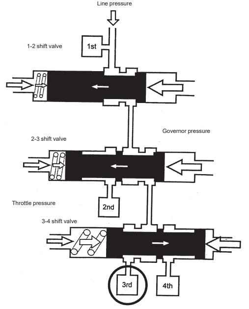
In such a case, the line pressure which exists at the top of the diagram is primarily applied to the 1st clutch, causing the1st gear to engage.
Then, because the condition of balance between [throttle pressure + spring force] and [governor pressure] within the 1-2 shift valve then causes the passage to be opened, hydraulic fluid can flow into the 2-3 shift valve.
Within the 2-3 shift valve, the passage to the second clutch is closed and the passage to the 3-4 shift valve is open; consequently, hydraulic fluid flows to the 3-4 shift valve without operating the 2nd clutch.
In addition, the 3-4 shift valve’s passage to the 4th clutch is closed while that to the 3rd clutch is open. As a result, the line pressure will be applied to the 3rd clutch and the 3rd gear will be engaged.
In accordance with this situation, although both the 1st and 3rd gear will be engaged, torque
will only be transferred by the latter due to the fact that the counter 1st gear is set to freewheeling at this time by the one-way clutch.
If the accelerator pedal were to be suddenly depressed while in this condition, the accompanying increase in the throttle-A pressure would cause valves to move to the right so
that either 1st or 2nd gear would be selected.
All other gears are selected in a similar manner to that detailed above.
Automatic Transmission Fluid (ATF)
A fluid known as “automatic transmission fluid” (or ATF) is used within an automatic transmission. This fluid functions as a hydraulic fluid inside both the torque converter and
the hydraulic control unit and as a lubricant inside the gear unit. In addition, ATF is directed
to all parts of the automatic transmission by an ATF pump.
Electronically-controlled Automatic Transmission
As its name suggests, an electronically-controlled automatic transmission (or E-AT)
combines the operation of an automatic transmission with electronic-type control. In such a
set-up, throttle opening and vehicle speed signals — which are conventionally communicated by hydraulic pressures — are detected in an electrical fashion. These and other signals are then used by the transmission control module (or TCM) to determine how the hydraulic control unit’s solenoid valves should be controlled. In this, it is possible to perform much more precise control of the transmission.
Furthermore, more advanced models can determine the type of road on which the vehicle is
currently travelling (i.e., whether it is level or inclined, etc.) and can control speed
accordingly
Post Comment