CVT Introduction
The Continuously Variable Transmission (CVT) operates on a similar basis as a general
automatic transmission and has achieved fuel economy similar to that of a manual transmission. The CVT can function virtually slip-free and allow the engine to remain in its optimal power range, which results in better fuel economy.
CVT operates in the lower range of ratios for better acceleration and increased engine braking.
“L” position is also used for engine braking while PCM/TCM utilizes the lowest range of CVT
ratios for increased climbing power.
CVT Operating Requirements
There are some basic operating requirements for any automatic transmission. The automatic
transmission MUST:
- Allow the engine to idle while the vehicle is at a stop and the transmission is in drive.
- Allow the vehicle to accelerate from a stop, especially when the vehicle is on a hill.
- Provide a succession of output ratios in order to allow the engine to use its maximum torque RPM range.
- Allow the vehicle to cruise at varying speeds while providing good fuel economy.
CVT Basic Operation
To manage the operation requirements, electronic components are used to control CVT.
Transmission Control Module (TCM) or Power Control Module (PCM) receives information from
sensors then actuates solenoids for the required operation. When the solenoids are activated,
ATF pressure is applied to the hydraulic valves, which makes the hydraulic valves shift to
engage/disengage clutches or to apply ATF pressure to the drive/driven pulleys.
Similar to the conventional AT, if there is a fault in the system, D4 light will flash to inform the
driver and will store DTC in the TCM/PCM. During a fault, CVT can still be driven safely.
For additional information about CVT control, refer to the CVT Technician Information Guide.
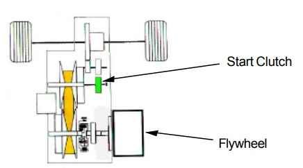
CVT does not use a Torque Converter but instead uses the Start Clutch for that function. This
requires TCM/PCM to control Start Clutch oil pressure, which makes it necessary to preform
Start Clutch Calibration in order to have proper TCM/PCM control.
CVT Speed Control
Drive and Driven Pulley
The Drive Pulley and the Driven Pulley are connected via the Steel Belt. Together, the pulleys
have the following functions:
- They provide a variable diameter to allow the belt to transfer power at various ratios.
- They maintain sufficient side pressure on the belt in order to prevent it from slipping, which can damage the belt and the pulleys.
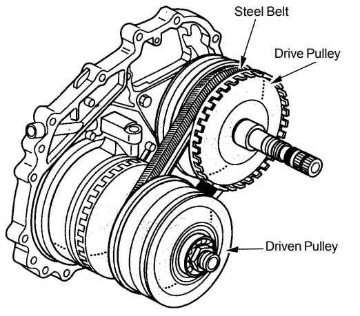
The drive pulley is mounted on the Input Shaft and is locked onto the Input Shaft in forward
position.
- In reverse position, the Drive Pulley turns in the opposite direction as in the forward position.
- The Drive Pulley pushes the belt, driving the Driven Pulley, which drives the Start Clutch.
- The Driven Pulley is directly mounted on the Driven Pulley Shaft.
- Each pulley has a section that is fixed and one that moves.
- The Steel Belt is located between the two sections of each pulley.
- Each pulley has springs that apply pressure to the movable section, forcing it towards the fixed part.
- The hydraulic system applies varied hydraulic pressure towards each pulley.
- The pulley ratio changes by applied spring force and fluid pressure to effectively alter the diameter of each pulley.
- The pulley ratio changes with engine speed to vary the drive ratios.
Pulley Ratios
To achieve different ratios, the effective pulley diameters change in reaction to the hydraulic
force and the force of the steel belt on the movable faces of the pulleys.
High Geared Ratio:
An increase in the Drive Pulley diameter and a decrease in the Driven Pulley diameter results in a higher ratio.
Low Geared Ratio:
A decrease in the Drive Pulley diameter and an increase in the Driven Pulley diameter results in
a lower ratio.
CVT Forward and Reverse
Planetary Gear Assy (‘00 Insight, ‘01-’02 Civic, ‘02 Jazz/Fit, ‘03 Civic Hybrid)
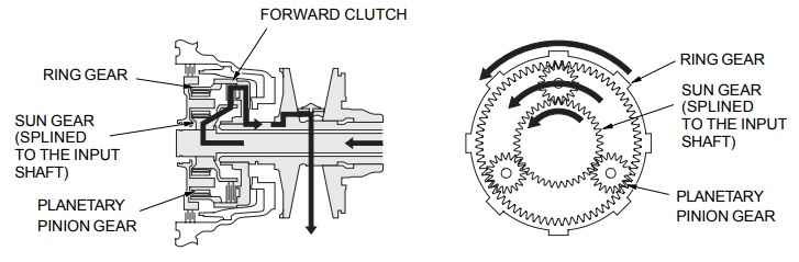
The Planetary Gearset Sun Gear is splined to the Input Shaft and forms the inner hub of the
Forward Clutch. The Single Gear type Planetary Gear Carrier engages the Sun Gear and forms
the inner hub of the Reverse Brake. The Ring Gear engages the forward Clutch Drum via tabs.
The outer hub of the Reverse Brake is formed from the Transmission Case.
Forward
When hydraulic pressure is applied to the Forward Clutch, the Forward Clutch creates
engagement between the Sun Gear and the Ring Gear. The Planetary Pinion Gear does not
rotate or revolve at this time allowing the Ring Gear and Sun Gear to rotate in the same
direction. The Sun Gear’s rotation, which is splined with the Input Shaft, is then transmitted to
the Drive Pulley Shaft via the Forward Clutch.
Reverse
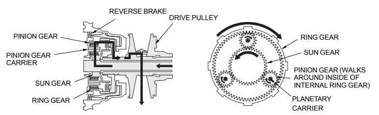
When the Forward clutch is released and the Reverse Brake pressure is applied, the Planetary
Carrier is locked to the Transmission Case and cannot rotate. The rotation of the Sun Gear is
transmitted to the Planetary Pinion Gears, which drives the Ring Gear in the opposite direction
of the Sun Gear. The Input Shaft is splined with the Sun gear and its rotation is transmitted to
the Drive Pulley Shaft in the reverse direction through the Forward Clutch Drum.
CVT Power Flow
“P” Position
In “P” position hydraulic pressure is not applied to the Start Clutch, Forward Clutch and the
Reverse Brake, and power is not transmitted to the Secondary Drive Gear. The Secondary
Drive Gear is locked by the Park Pawl interlocking the Park Gear.
“N” Position
Engine power transmitted from the flywheel drives the input shaft, but hydraulic pressure is not
applied to the Forward Clutch and Reverse Brake. Power is not transmitted to the Drive Pulley
Shaft. Also hydraulic pressure is not applied to the Start Clutch.
“D”, “S” and “L” Position (Forward Range)
- Forward Clutch engages.
- Reverse Brake releases.
- Start Clutch engages.
- Hydraulic pressure is applied to the Forward Clutch and the Start Clutch, and the Sun Gear drives the Forward Clutch.
- The Forward Clutch drives the Drive Pulley Shaft, which drives the Driven Pulley Shaft linked by the Steel Belt.
- The Driven Pulley Shaft drives the Secondary Drive Gear via the Start Clutch.
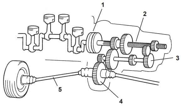
- Power is transmitted to the Secondary Driven Gear and the Final Drive Gear, which in turn drives the Final Driven Gear.
“R” Position (Reverse Range)
- Forward Clutch releases.
- Reverse Brake engages.
- Start Clutch engages.
- Hydraulic pressure is applied to the Reverse Brake and the Start Clutch, and the Planetary Carrier locks with the Reverse Brake.
- The Sun Gear drives the Planetary Pinion Gears to rotate, and the Planetary Pinion Gears drive the Ring Gear in the opposite direction from the rotation direction of the Sun Gear.
- The Ring Gear drives the Drive Pulley Shaft via the Forward Clutch Drum, and Drive Pulley Shaft drives the Driven Pulley Shaft linked by the Steel Belt.
- The Driven Pulley Shaft drives the Secondary Drive Gear via the Start Clutch.
- Power is transmitted to the Secondary Driven Gear and the Final Drive Gear, which in turn drives the Final Driven Gear.
CVT Service Talks
Overview
The procedure allows the PCM/TCM to store a base MAP sensor signal which indicates that it
is applying the right amount of pressure to the start clutch – enough for the right amount of
creep, but not so much as to stall the engine.
When is calibration be needed?
If PCM/TCM’s memory is erased, either from battery replacement, backup fuse removal or
cutting the power off for maintenance, you must perform a Start Clutch Calibration. Also, if the
maintenance was performed on the Start Clutch (e.g. removal, replacement), the calibration
should be performed in order to match the CVT to the control system.
Major reasons for a Start Clutch Calibration:
- Removal, replacement or overhaul of the transmission assembly
- Replacement of the start clutch assembly
- Removal or replacement of the lower valve body assembly
- Removal, replacement or overhaul of the engine assembly
- Replacement of the battery
- After resetting PCM (PCM and TCM can be reset individually)
- Removal, replacement or resetting of PCM/ECM
- Flashing of ATF
NOTICE:
If a Start Clutch Calibration is not performed after the above maintenance, some malfunctions
may occur, such as these:
- Engine speed will drop off, and stall (in any drive position).
- Fluctuation in engine speeds (in any drive position).
- Judder when accelerating from a stop.
Calibration may be performed more than once in order to increase Start Clutch performance.
Start Clutch Calibration
There are two kinds of major calibration procedures, and there are sub procedures for the
different specified models. First see below table, then refer to each model’s shop manual.
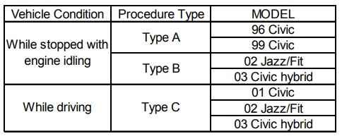
NOTE:
Start Clutch Calibration should be performed under any condition (bad weather, storm, etc.). If
the calibration is performed in the rain, electric equipment such as windsheild wipers will create
electrical load. In this case, you may perform Start Clutch Calibration while stopped with engine
idling.
ATF
The CVT, especially the belt and pulley surfaces, is very susceptible to dirt. The components will be quickly damaged by impurities in the ATF so be careful about cleanliness when servicing the transmission, including any time that a passage into the transmission is opened. This would
include ATF changes, ATF pan removal, ATF cooler hose removal and driveshaft replacement.
Only Honda genuine ATF-Z1 should be used. Using improper ATF could degrade CVT
performance, such as causing judder or whine when accelerating from a stop. Honda genuine
ATF-Z1 allows anti-judder protection as well as smoother starting and shifting low temperature
environments.
Post Comment