Adaptive Cruise Control Introduction
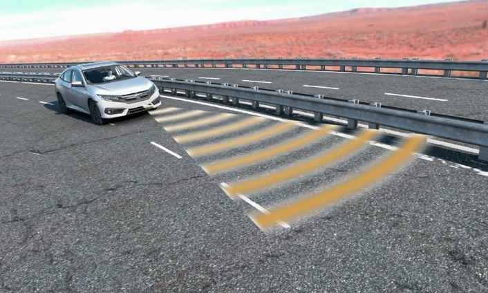
Cruise control is a desirable accessory, but in traffic, drivers must continually cancel cruise control to adjust for cars in front of them.
Adaptive cruise control, or ACC, helps to address this issue. ACC uses a front mounted radar assembly to detect other vehicles, and automatically adjusts vehicle speed to place the car at a fixed following distance. Once the lane clears, the system then returns the vehicle to the system set speed.
Once you’ve read this article, you’ll be able to:
Explain the purpose of Adaptive Cruise Control.
Explain the construction and function of Adaptive Cruise Control.
And Identify the critical steps to the radar aiming procedure.
Adaptive Cruise Control Basic Setting
The ACC control unit includes direct connections to a millimeter wave radar and a brake light relay.
In addition, the ACC unit communicates with the Gauge Control Module, VSA Modulator-control Unit, PCM, Electric Parking Brake Control Unit, Steering Angle Sensor, and SRS Unit using the F-CAN network.
Drivers operate the ACC system using controls on the steering wheel, and receive system information and warnings from the gauge assembly. To turn the system on and off, the steering wheel includes an “MAIN” switch.
Note: Some models may also have a “ACC” switch.
Pressing this switch energizes the controller but does not engage the cruise control.
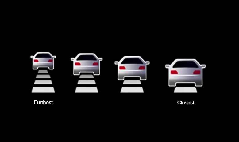
A DISTANCE button located on the steering wheel allows the driver to choose a following
distance (in seconds).
Pressing the button cycles through the available following distances.
One bar represents the closest following distance, and 4 bars indicates the greatest distance.
Adaptive Cruise Control Speed Setting
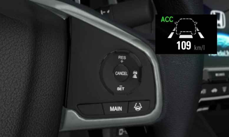
To engage Adaptive Cruise Control, the system must be on, with vehicle speed between 40 km/h and 145 km/h.
Within this speed range, pressing the “SET” button engages Adaptive Cruise Control.
The set speed appears in the MID along with a vehicle icon indicating system status.
If the vehicle icon appears in outline form, the lane is open and the vehicle maintains the set speed.
A solid icon indicates the presence of a vehicle in the lane of travel.
The Gauge Module still indicates the set speed, but the actual speed matches the lead vehicle.
Once the lane opens up, the vehicle icon returns to outline form, and the speed value flashes while the vehicle accelerates back to the set speed.
During operation, the driver can modify the set speed using the steering wheel controls.
Briefly pressing the RES/Plus switch increases the set speed by one km per hour.
Holding the “RESUME” or RES+ button until a beep sounds (about one second) increases the set speed to the next multiple of 5.
Briefly pressing down on the SET/Minus rocker switch decreases the set speed by one km per hour.
Holding Set/- (about one second) button decreases the set speed to the next multiple of 5.
Adaptive Cruise Control other Input
As with conventional cruise control systems, accelerator and brake inputs override any ACC settings.
Pressing on the accelerator pedal increases vehicle speed, and releasing the pedal allows the vehicle to coast back to the set speed.
Pressing the brake pedal (or CANCEL button) suspends ACC operation and the vehicle icon and set speed disappear.
However, the system does retain the current set speed in memory.
Return to the set speed by pressing the RES+ (Resume) button with the vehicle speed above 40 km/h and an open lane.
Pressing the MAIN switch turns off adaptive cruise control and also clears the set speed.
The system also supports normal cruise control.
To activate this option, press and hold the DISTANCE button until “Cruise Mode Selected” appears in the MID (about two seconds).
In this mode, the cruise control maintains the set speed with or without traffic in the travel lane.
During operation, a box reading “CRUISE MAIN” appears in the MID, and no vehicle icon or set speed appears.
To return to Adaptive Cruise Control, press and hold the DISTANCE button again until “ACC Mode Selected” appears in the gauge control module.
Adaptive Cruise Control Constuction
The ACC System has three new components compared to conventional cruise control.
An ACC Unit,
Millimeter Wave Radar and a Brake Light Relay also called the ACC Relay.
The Millimeter Wave Radar and the Brake Light Relay connect directly to the ACC Unit.
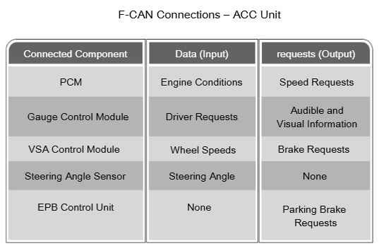
The ACC Unit receives data (inputs) and sends requests (outputs) using the F-CAN Network.
This chart shows the ACC Unit data connections, along with the related inputs and outputs.
PCM data provides engine operating parameters, and the ACC System sends it speed requests.
The Gauge Control Module provides driver request information, and the ACC Unit sends back system information and warnings.
The VSA Modulator-control Unit provides the ACC System with wheel speed data, and receives brake requests when the ACC System adjusts vehicle speed.
The Steering Angle Sensor provides steering angle Information, but does not receive outputs from the ACC System.
Finally, the Electric Parking Brake Control Unit engages the parking brake when requested.
Adaptive Cruise Control Radar Design
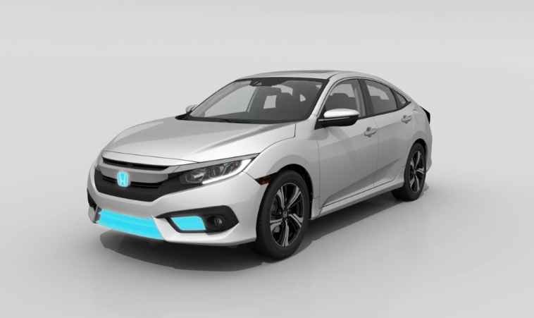
The location of the Millimeter Wave Radar will vary from vehicle to vehicle. It may be centered or offset in the front grill or located under the bumper.
It sends out a burst of radio waves
that reflect back to the Millimeter Wave Radar.
Based on the length of time it takes the reflection to return to the unit, the radar can determine distance.
By making these measurements many times a second,
the radar can determine if a car is moving closer, maintaining distance, or moving away.
Using this information, the ACC Unit modifies the vehicle speed by making throttle requests to the PCM,
or brake requests to the VSA Modulator- control Unit.
When the ACC Unit sends a brake request, it also energizes the Brake Light (ACC) Relay to illuminate the brake lights.
Adaptive Cruise Control Low Speed Follow
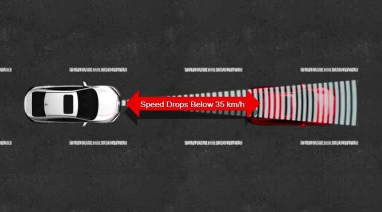
On the first generation Adaptive Cruise Control system,
if the leading vehicle speed dropped below 35 km/h (22 mph),
the system turned off.
Speeds below this threshold require unique distance control
and requires the braking system to stop the vehicle.
Older systems did not have the software required to manage these needs.
Starting with the 2016 Civic, Adaptive Cruise Control systems also include a Low Speed Follow or LSF feature.
This system is designed to operate at speeds below 40 km/h,
and permits Cruise Control operation in stop and go traffic.
The system uses the ACC radar sensor and controller,
but uses unique driver inputs during system operation.
These systems have a unique control region between zero and 40 km/h.
The driver cannot engage the system below 40 km/h, unless there is a vehicle in front of the car.
Above this speed, the Adaptive Cruise Control System operates normally.
The LSF system can use the VSA system to bring the vehicle to a full stop,
and indicates the stopped mode by displaying “”Stopped”” in the gauge control modules.
Once in the stopped mode, the vehicle will not move without additional input.
When the front car begins to move,
the driver must press resume or set on the steering wheel switch,
or lightly tap the accelerator pedal to re- engage cruise control.
These re-engagement steps must be repeated each time the vehicle comes to a full stop.
The LSF system requires a lead car in radar range to operate between zero and 40 km/h.
If the lead vehicle moves out of range while in the stopped mode,
the system suspends cruise control.
Pressing the set or resume switch will not restart the vehicle.
So the driver must use the accelerator to move the vehicle.
In addition, if the lead vehicle turns out of the lane at speeds below 40 km/h,
the Cruise Control system suspends operation.
The driver must use the accelerator to get back up to speed,
and must re-engage cruise control when the vehicle exceeds 40 km/h.
Adaptive Cruise Control Brake Control
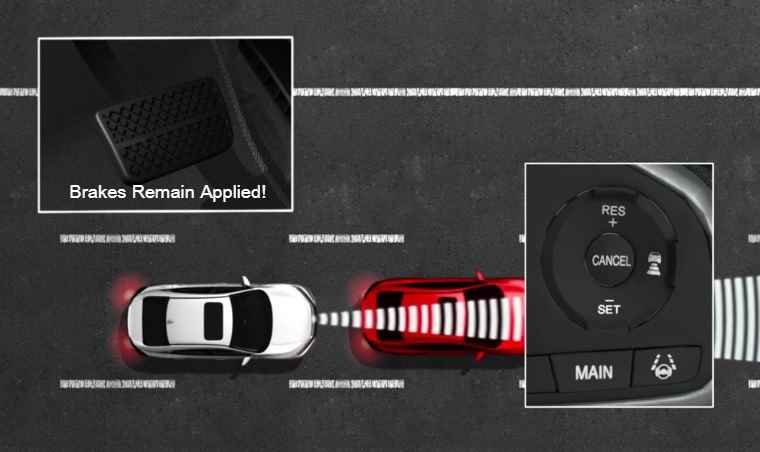
When the LSF system brings the vehicle to a full stop, In addition to “Stopped” appearing in the gauge control module, the brakes remain applied until the vehicle is placed in park, or the driver provides a start request.
If the system sees a set or resume switch input with a car still stopped in front of the vehicle, the system stops the vehicle before it rolls into the stopped car.
Likewise, if the driver presses the cancel switch with the vehicle stopped, the brakes also remain applied, and the MID displays a message reading “Cruise Cancelled Apply Brake Pedal”.
If the driver removes their seatbelt while in the stopped mode, the LSF system sets the electric parking brake (on cars equipped with an Electric Parking Brake), or turns on a MID warning for cars with manual parking brakes.
For safety reasons, turning off the main switch always shuts down cruise control.
For this reason, if the main button is pressed while in the stopped mode, The system turns off, and the car may roll forward (or backward) into a stopped car.
Adaptive Cruise Control Troubleshooting
If the ACC system has a malfunction, a fault message appears in the MID.
There are two types of ACC system failures, temporary and permanent.
Temporary failures typically refer to external issues, rather than system faults.
Environmental issues (weather, road or vehicle conditions) can affect radar performance, suspending ACC operation.
When these external factors occur, “ACC OFF” briefly appears in the MID, and the vehicle icon and set speed then disappear.
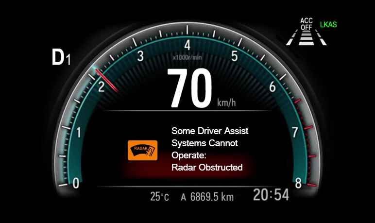
Excessive dirt or debris on the face of the Millimeter wave radar can affect operation.
To inform the driver, this image appears in the MID.
To help reduce comebacks, make sure the customer understands ACC system operation.
Be sure they understand that normal environmental factors affect ACC operation, and can cause temporary ACC system shutdowns.
If customer indicates the cruise control maintains speed, but does not adjust to traffic, first check the car.
If the guage control module displays “CRUISE MODE,” with the ignition on and main button pressed, the system is in regular cruise control mode, rather than active cruise control.
If this occurs, explain how to activate the ACC System.
Permanent failures occur when faults in the ACC system or supporting vehicle systems set a DTC.
These failures display “Adaptive Cruise Control Problem” in the gauge control module, and the system sets an Adaptive Cruise Control DTC.
Refer to the shop manual DTC troubleshooting to repair these faults.
Adaptive Cruise Control Radar Aiming
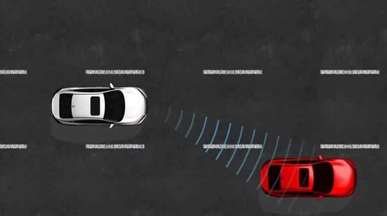
Anytime the Millimeter wave radar is replaced, or body damage moves the mounting point, an aiming error may occur.
If the radar points to the side, it detects vehicles in the other lanes, causing the vehicle to slow down and/or brake despite an open travel lane.
If the radar points down or up, it can miss vehicles in the lane.
Because of these issues, the Millimeter wave radar may require aiming.
Note: If the trunk is loaded with very heavy objects, a correctly aimed unit may still point upward and miss low profile vehicles.
Cruise Control Radar Aiming Check
Radar aiming requires a flat, open space about 10 m deep and 4.5 m wide in front of the vehicle.
If the space is sloped for drainage, the rise or drop cannot exceed 1% (18 cm in 10 m).
To prepare the vehicle for aiming adjustment:
Check for modifications to the vehicle’s suspension or other problems with the vehicle ride height including excessive weight in the trunk.
Make sure no tires rest on a high spot such as a floor cover plate or equipment ramp.
Check the air pressure of every tire. If needed, adjust the air pressure of all tires to specification.
Check the front grill and bumper for damage or loose mounting points.
If needed, clean the face of the Millimeter wave radar. Remove foreign substances such as dirt, ice, or insect remains.
Position the steering wheel to straight ahead. Do not move the steering wheel once it is set.
Place the shift lever in the Park position and set the parking brake.
Once the vehicle is ready for aiming, follow the shop Manual aiming procedure.
Post Comment