1. CMBS Introduction
Most rear end collisions are thought to happen as a result of delayed recognition where the driver fails to notice the vehicle in front is braking, or a delayed response by the driver. To compensate for this, Honda has developed the collision mitigation brake system, or CMBS (Collision Mitigation Braking System).
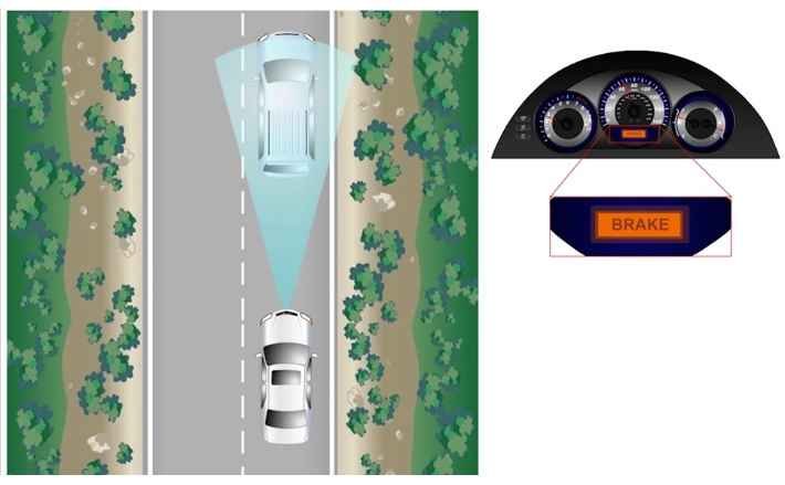
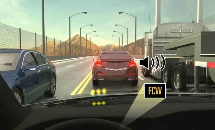
CMBS detects vehicles ahead using radar and calculates distance, relative speeds, and anticipated vehicle path to determine the likely hood of a collision. If the system determines a collision is likely, it flashes a visual warning and sounds an alarm to prompt the driver to take action. If at this point, the driver applies the brakes appropriately, a collision can generally be avoided.
If the driver takes no action, the system helps reduce the impact on occupants and vehicle damage by slowing down the vehicle during the last couple of seconds before the collision. It does not avoid a collision. It only mitigates or reduces the severity of the impact. The driver still has control to avoid the collision.
2. CMBS Operation
Let’s look at how the collision mitigation system operates. As explained before, the system does not avoid an accident, it only reduces the severity of the impact.
Statistically, most rear end collisions happen at lower speeds, therefore, the system works best at speeds below 56km/h than at higher speeds since there is more time to react to the initial warning given by the system.
The system is always ON, unless it is turned off using the CMBS off button. If it is turned off, the CMBS indicator in the instrument panel comes on and stays on and CMBS OFF is shown in the MID as a reminder the system is off.
When approaching the other vehicle or object, the system will calculate what the minimum safe distance should be and compare this distance to the actual distance and reacts in three stages.
At stage 1,
or approximately 3 seconds before a collision is about to happen, the system recognizes an accident is about to happen.
At stage 2,
or approximately 2 seconds before the collision, the system still recognizes an accident is about to happen and provides further warning.
At stage 3,
or approximately 1 second before the collision, the system recognizes there is a limited amount of time to avoid the accident.
At stage 1,
the system prompts the driver to take preventative action by flashing a BRAKE visual warning in the MID and sounding an alarm.
At stage 2,
the system provides further warning by lightly retracting and releasing the driver’s seatbelt with E- Pretensioner and lightly applying the brakes. Please note that the seatbelt retraction and release is not applied during stage 2 if the other vehicle is stationary.
At stage 3,
the system strongly applies the brakes and strongly retracts the front seatbelts to hold the driver and front passenger in place as it prepares the vehicle for an impact with E- Pretensioner.
*The seat belt retracting function is limited to vehicles equipped with the E- Pretensioner function.
CMBS Limitations
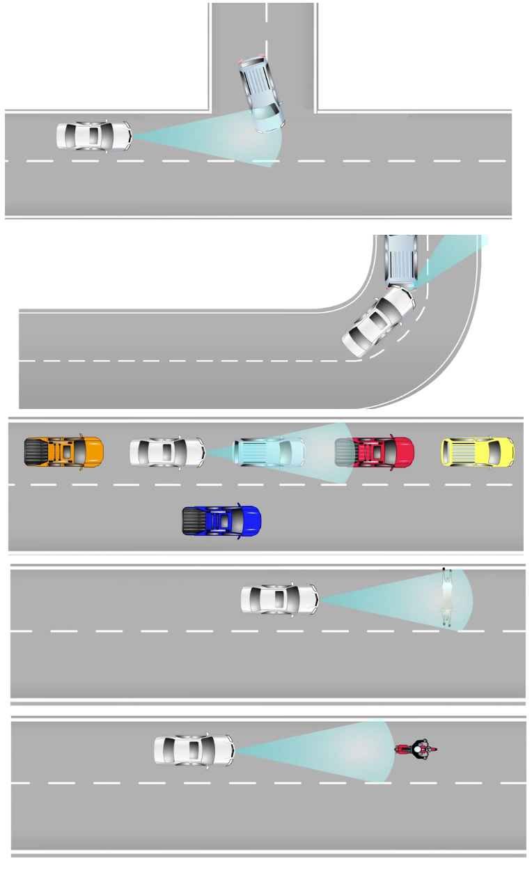
There are some limitations where CMBS may not work. Among them are:
When a vehicle suddenly converges in front of you.
When a vehicle is around a blind corner.
When the vehicle is not all the way in a lane.
When the vehicle is too close to another vehicle and moving under 16km/h.
When the vehicle is too close to another vehicle and suddenly accelerates.
When the vehicle moves forward from a stop.
When a pedestrian or animal rushes out from the side.
When the vehicle approaches a bicycle or motorcycle with low reflection.
And when the driver tries to avoid the accident by braking or steering.
CMBS Unwanted Operation
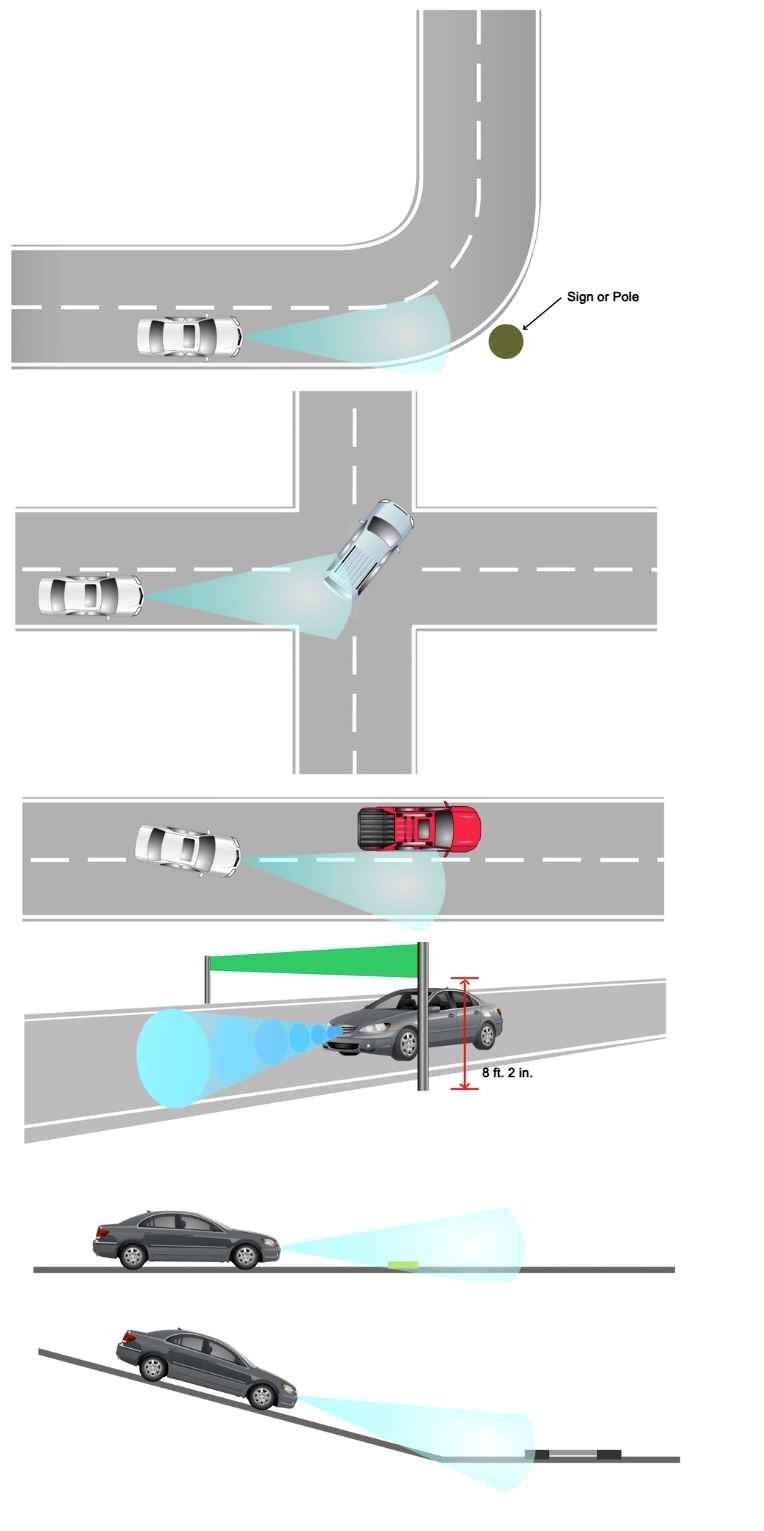
There are also situations when CMBS will operate when not wanted. Among them are:
When there is a sign or post standing at the entrance to a curve.
When the vehicle is too close to a forward vehicle that is turning.
When passing a forward vehicle too closely.
When passing through a gate at high speed.
When passing over a speed bump with a squared off shape at high speed.
And when coming up to some rails at the bottom of a hill.
3. CMBS Functions
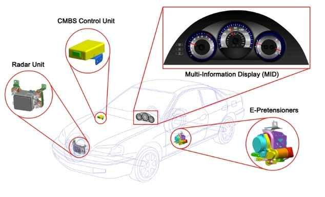
The CMBS has three basic components.
The CMBS control unit, the radar unit, and the E-pretensioners. Information from the system is shown in the multi- information display, or MID of the gauge control module.
Please note that in some vehicles, ACC is combined with the collision mitigation braking system, or CMBS, into one control unit. Both systems use the radar unit to achieve the desired results.
*Specifications vary depending on the vehicle. For details, please refer to shop manual.
CMBS Contro Unint
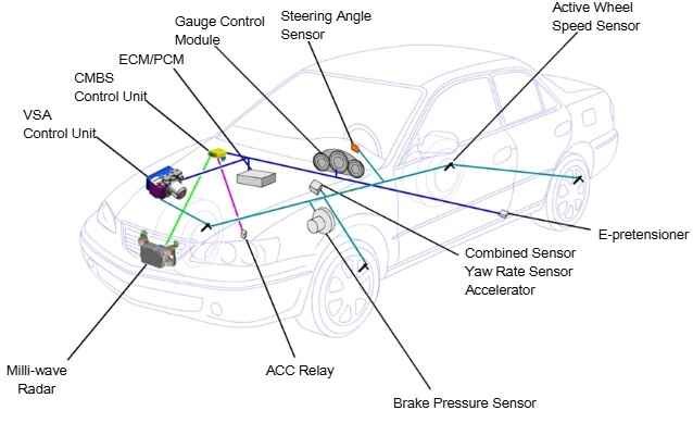
The CMBS control unit is located near the glove box and communicates with other systems via F-CAN to get sensor information and other system’s status to determine the driving conditions of the vehicle.
The inputs to the control unit are data from the radar unit to determine the distance to the vehicle ahead and measure relative speeds and data from the yaw rate sensor, steering angle sensor, and wheel speed sensors to determine driving conditions.
The outputs from the control unit are to the VSA control unit to activate the brakes.
When VSA brake activation takes place, a brake pressure sensor is used to activate the brake lights via the ACC relay.
*Specifications vary depending on the vehicle. For details, please refer to shop manual.
CMBS Radar Unit
The radar unit is located front Bumper inside. It sends out a beam that comes back to the unit to determine the distance between the vehicle and another vehicle or object ahead. This information is then sent to the control unit.
OK now, let’s try to explain how this radar works. As an example, let’s look at the speed of sound to determine a distance. When you shout into a well, the sound of your shout travels down the well and is reflected, or echoes off the surface of the water at the bottom of the well. If you measure the time it takes for the echo to return and if you know the speed of sound, you can calculate the depth of the well fairly accurately. Radar uses radio waves instead of sound. Radio waves travel far, are invisible to humans, are easy to detect even when they are faint, and travel at the speed of light. Now we can apply the sound example to radar. The radar set turns on a transmitter and shoots out a short, high-intensity burst of high-frequency radio waves. The burst might last a microsecond. The radar set then turns off the transmitter, turns on a receiver and listens for an echo. The echo comes from the radio waves hitting an object and bouncing off, and the radar measures the time it takes for the echo to arrive to determine the distance.
E-Pretensioner
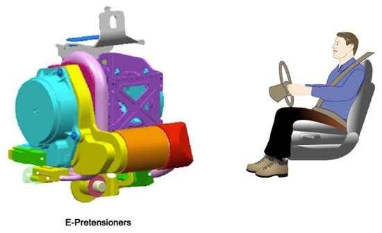
The E-pretensioners are part of the seatbelt retractor mechanism. They are used to lightly retract and release the driver’s seatbelt during stage two, and then completely tighten up the driver’s and front passenger’s seatbelts during stage three.
4-Radar Aiming
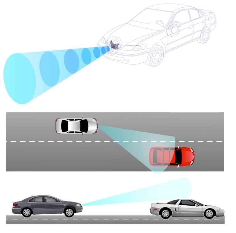
Radar Alignment Critical
The addition of the radar unit to the front of the vehicle adds some
challenges when repairing vehicles with front end damage. After the radar unit is replaced or detached and re-attached, or if an aiming error occurs in the radar unit, the radar aiming will need to be adjusted so that the system operates properly.
An incorrect position of the radar unit will cause the system to react abnormally and generate customer complaints.
A wrong or loose mounting of the radar on its horizontal axis will point the radar waves to the left or to the right. In this case, the radar will not detect vehicles in front of you, but rather in the lane next to you, causing the system to brake the vehicle as you approach them.
A wrong mounting of the radar on its vertical axis will point the radar waves to the sky or to the ground. In this case, the system will never react or react continuously. Also note that if the trunk is loaded with very heavy objects and the front end is pointing upward, it is possible that the radar will be pointing up and may not react to low objects in front.
Radar Aiming Special Tools
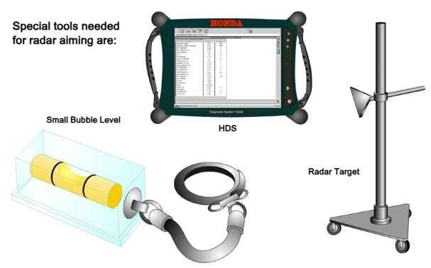
The special tools needed for radar aiming are:
- The HDS.
- A radar target.
- And a commercially available small bubble level for vertical aiming.
Radar aiming Preparation
To prepare the vehicle for aiming adjustment:
Make sure the vehicle’s suspension has not been modified.
Unload all the cargo from the vehicle.
Check the air pressure of every tire. If it is uneven, adjust the air pressure of all tires to specification.
Make sure the front grill and bumper are securely in place.
Make sure the front surface of the grill emblem is clean. Remove any foreign substance such as dirt, mud, snow, or ice.
Place the vehicle in the specified area with 10m in front, or 5m using radar absorbing material.
Position the steering wheel for straight ahead. Do not move the steering wheel once it is set.
Place the shift lever in the Park position and set the parking brake.
Make sure that all four of the vehicle’s tires contact the floor and that none of them are on anything such as an iron plate or roller.
* For details, please refer to shop manual.
Radar Vertical Adjustment
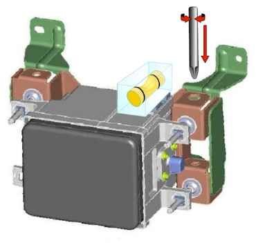
To check the radar vertical aiming, place a level on the level reference part of the radar unit. If it is not level, rotate the adjustment bolt until the level gauge shows the unit is level.
* For details, please refer to shop manual.
Radar Auto Horizontal Aiming
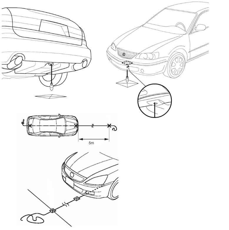
To perform auto horizontal aiming:
Mark the center of the vehicle in front and back.
Place a string along the two marks and extend it about 5m in front of the vehicle.
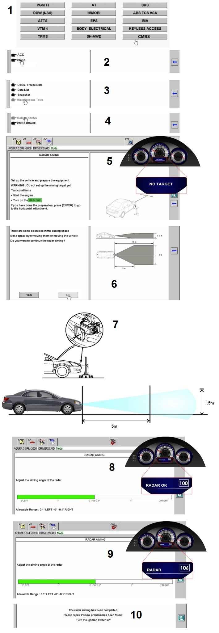
Connect the HDS and select CMBS from the System Selection Menu. From the CMBS Menu, select Miscellaneous Tests, and then RADAR AIMING. After you get to the preparation screen for radar aiming, please note that the MAIN SWITCH is the ACC button. As noted, the aiming target should not be set in front of the vehicle at this time.
Confirm that the MID shows “No target” and the HDS confirms that there nothing in front of the radar. If there is, the HDS will indicate there is something in front of the vehicle.
Adjust the height of the radar aimer to the same height as the radar unit.
Place the radar aimer at the about 5m mark in front of the vehicle.
Confirm that the radar aiming
allowance in the MID is 100 plus or minus 1 and that the radar aiming is O degrees on the HDS. If the MID does not read 100 plus or minus 1, auto aiming cannot be performed because the radar has too big an offset, therefore a manual horizontal adjustment must be done.
When finished, press ENTER and the HDS confirms that auto aiming is complete.
* For details, please refer to shop manual.
CMBS Radar Manual Horizontal Adjustment
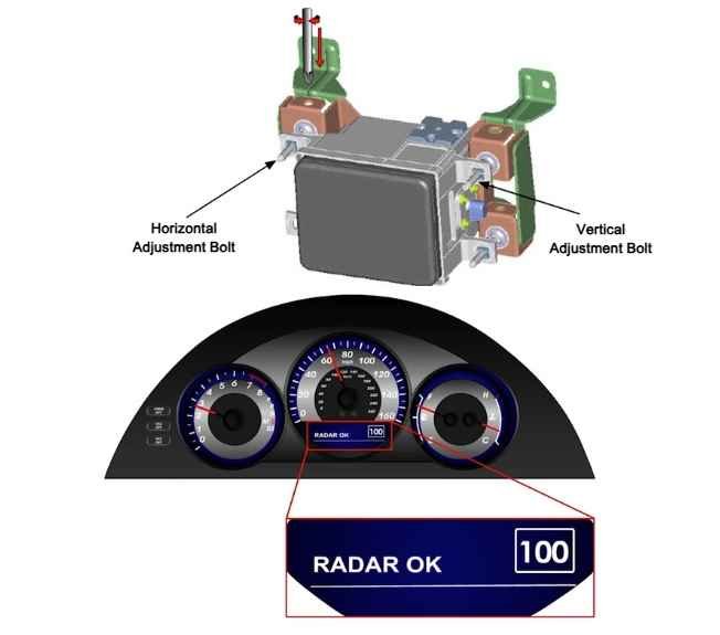
To perform a manual horizontal adjustment if needed, adjust the radar unit by turning adjustment bolt while checking the MID. Adjust the radar unit until the MID reads 100.
* For details, please refer to shop manual.
Post Comment