-
Lane Keeping Assist System & Lane Departure Warning Introduction
The Lane Keeping Assist System, or LKAS, is designed to assist drivers with steering in order to keep the vehicle in the lane of travel.
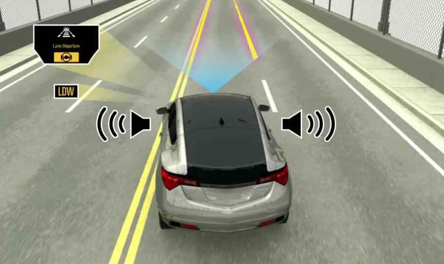
LKAS also includes a Lane Departure Warning, or LDW, function that warns the driver when the vehicle is departing the identified lane of travel.
Separate buttons allow the driver to enable or disable the LKAS and LDW functions individually.
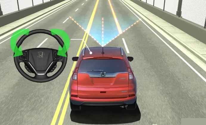
Both functions are provided by identifying lane markings using an integrated camera to identify and monitor the vehicles lane of travel.
LKAS provides steering torque to keep the vehicle in the lane.
This additional steering assist helps reduce driver fatigue.
LDW alerts the driver with audible and visual warnings when the vehicle begins to depart the lane of travel.
The LDW function does not provide any driving assistance.
In this article, you will learn about the Lane Keep Assist System, including the system components, system operation, and service considerations.
At the end of this module, you will take a test to evaluate what you’ve learned.
2. LKAS & LDW System Components
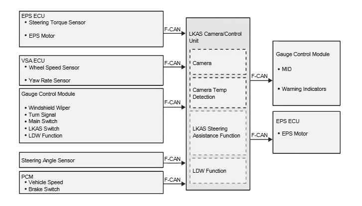
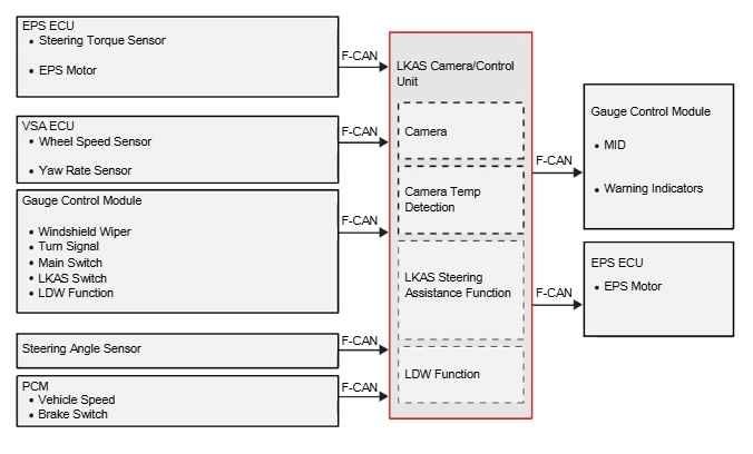
LKAS & LDW System Diagram
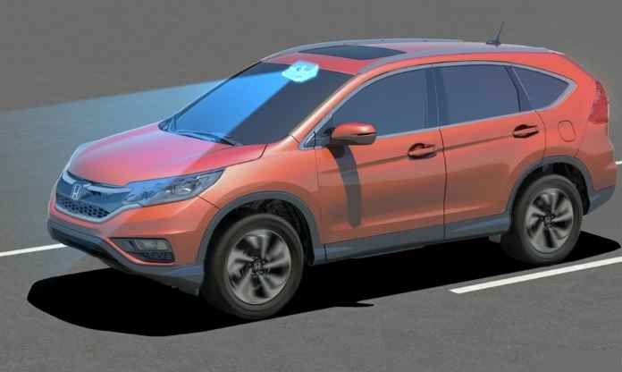
LKAS System Front Camera
This system includes the LKAS Camera/Control Unit which includes the camera and control function.
The LKAS Camera/Control Unit mounts behind the rear view mirror on the windshield.
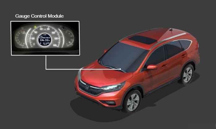
LKAS System Gauge Contro Module
Gauge Control Module inputs and outputs, which include LKAS steering wheel buttons, turn signals, windshield wipers and indicator lamps.
The Gauge Control Module is contained in the instrument cluster.
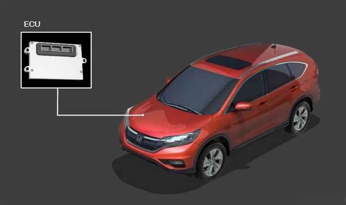
LKAS System EPC ECU
Electric Power Steering ECU inputs & outputs, which include the steering torque sensor and brushless electric power steering motor.
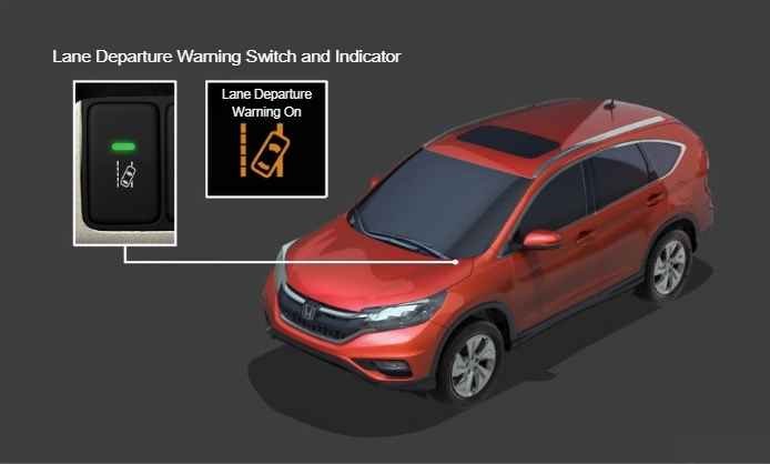
LKAS System On/Off Switch
LDW Switch & Indicator.
The LDW switch and indicator light is located on the driver side lower portion of the dashboard.
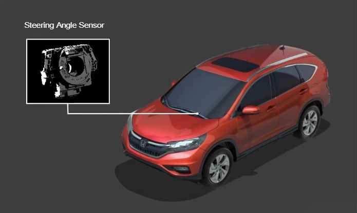
Steernig Angle Sensor
Steering Angle Sensor.
The steering angle sensor is located on the steering column, behind the steering wheel.
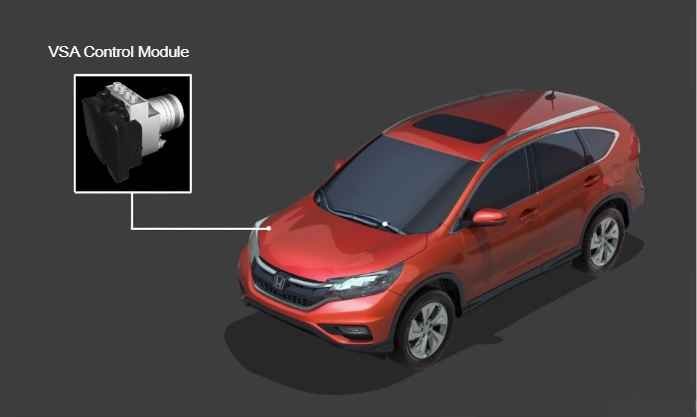
VSA Control Module
VSA control module inputs, which includes yawrate sensor and wheel speed sensors. The VSA control module is located in the engine compartment.
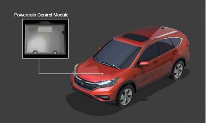
Power Control Module
The Powertrain Control Module outputs, which include vehicle speed, brake input and SCS.
The powertrain control module is located in the engine compartment.
3. LKAS & LDW System Operation
Normal
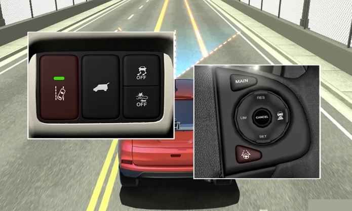
Lane Keeping Assist and Lane Departure Warning can both be active at the same time, or either function turned on or off individually.
Separate switches allow the driver to enable or disable the LKAS and LDW functions individually.
Normal Operation: LKAS Part 1
LKAS provides active control at speeds between 72km/h (45mph) and 144km/h (90mph).
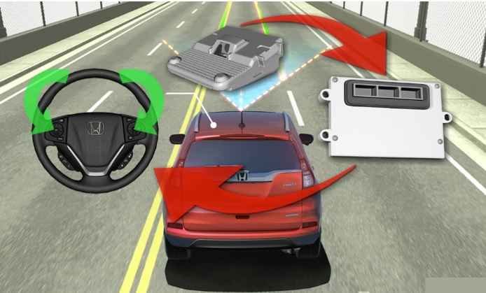
While LKAS is active, the integrated camera continuously identifies lane markings, and provides steering torque as needed to keep the vehicle in that lane.
The LKAS Camera/Control Unit instructs the Electric Power Steering control unit to provide steering assist to accomplish this.
Normal Operation: LKAS Part 2
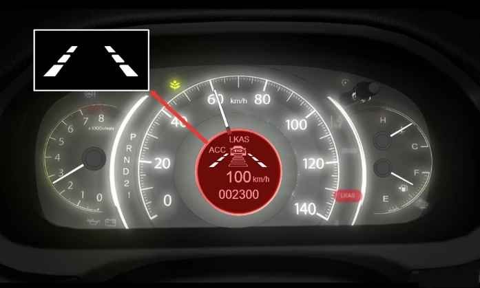
When the cruise control main power is on, the MID displays LKAS, and in the instrument panel the LKAS indicator is green.
The MID displays lane outlines when the system is not assisting the driver.
Solid lanes are displayed when the system is actively providing assistance to the driver.
Normal Operation: LKAS Part 3
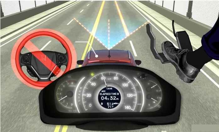
The LKAS Camera/Control Unit receives signals from the EPS ECU, Gauge Control Module, VSA Control Module, Steering Angle Sensor and PCM to determine if the driver is actively controlling the vehicle or not.
The LKAS function uses all of these signals to suspend operation if the driver is controlling the vehicle.
The LDW function uses only the turn signal and brake switch signals to determine active driver input.
LKAS Operation Disable/Enable
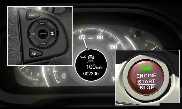
The LKAS system is disabled by pressing the button on the steering wheel.
When the system is disabled, the lane marking indicators disappear from the MID.
LKAS is turned back on by pressing the button again.
LKAS defaults to OFF at each ignition cycle.
LKAS Normal Operation
The LDW function operates between speeds of 64kmh and 145km/h (40mph and 90mph).
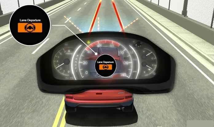
This function alerts the driver when the system detects the possibility of the vehicle departing the identified lane of travel to the left or right.
If the vehicle begins to leave the lane in either direction, messages appear in the MID, and an audible warning is issued.
Lane Departure warnings continue for a maximum time of 1.6 seconds.
LWD Operation Disable Enable
To disable or enable the Lane Departure Warning System, the LDW switch must be pressed.
When the system is disabled, the indicator light on the button turns off.
At each ignition cycle, the LDW system remains in the mode it was last in.
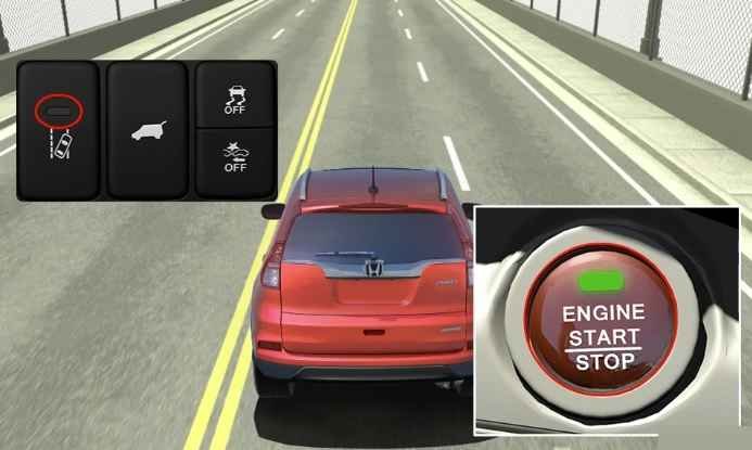
LKAS/LDW System Suspension
LKAS or LDW will not function if environmental conditions prevent the camera from clearly identifying lane markings for example, if lane markings are faded or covered by snow or dust.
LKAS will function when the windshield wiper Auto function is used or when set to Intermittent, However the system will suspend operation if the windshield wipers are being used in the LO or HI setting.
In addition, the LDW function will not issue lane departure warnings when the vehicle enters sharp curves.
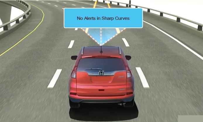
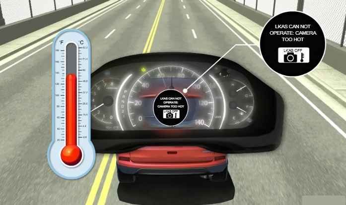
KAS/LDW System Camera too Hot
If the LKAS Camera/Control Unit becomes too hot, A warning message is displayed in the MID that the camera is hot and cannot operate.
The system will resume operation when the camera temperature is within operating specifications.
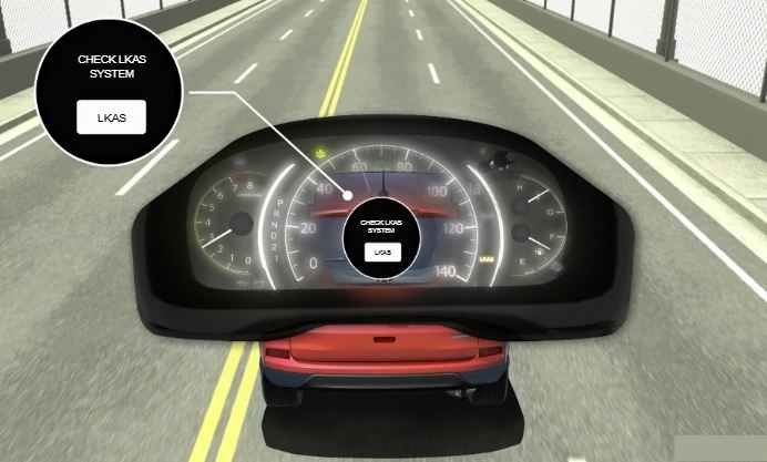
LKAS/LDW Failure Notification
The LKAS Camera/Control Unit contains internal self diagnostics.
When a failure is detected with the LKAS function, the system displays a message in the MID and the LKAS indicator becomes amber.
The system DTCs can be accessed using the Scanner.
LKAS/LDW Control
LKAS/LDW Control 1
To control the Lane Keeping Assist System, the LKAS Camera/Control Unit receives information from its integrated camera, VSA Control Module, PCM, EPS ECU, Steering Angle Sensor and Gauge Control Module.
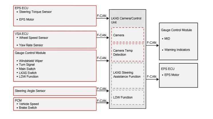
LKAS/LDW Control 2
The LKAS Camera/Control Unit sends commands to the Gauge Control Module to issue display LKAS status and issue warnings, and to the EPS ECU to provide steering assist.
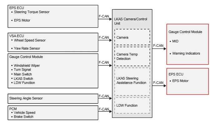
LKAS/LDW Control 3
The LKAS Camera/Control Unit contains all Lane Departure Warning logic within the module.
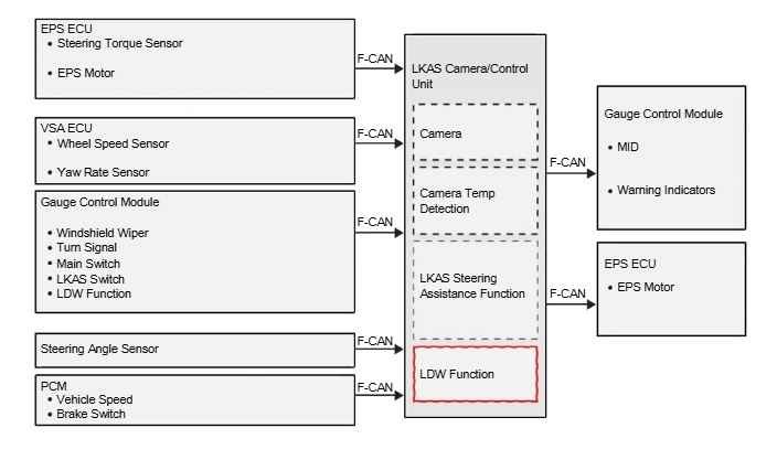
LKAS Operation Part 1
The cruise control main switch enables the LKAS system and the gauge control module displays LKAS system messages in the MID.
The camera identifies lane markings.
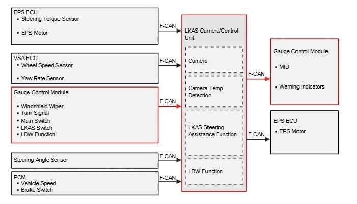
LKAS Operation Part 2
Pressing the LKAS switch initiates the LKAS steering Assistance function and displays lane outline markings in the MID.
Vehicle speed and brake switch
information is received from the PCM.
Wiper information is received from the Gauge Control Module.
Wheel speeds and yaw rate information are received from the VSA ECU.
Steering angle information is received from the steering angle sensor.
Driver steering input is received from the steering torque sensor via the EPS ECU.
Lane position information is received from the camera.
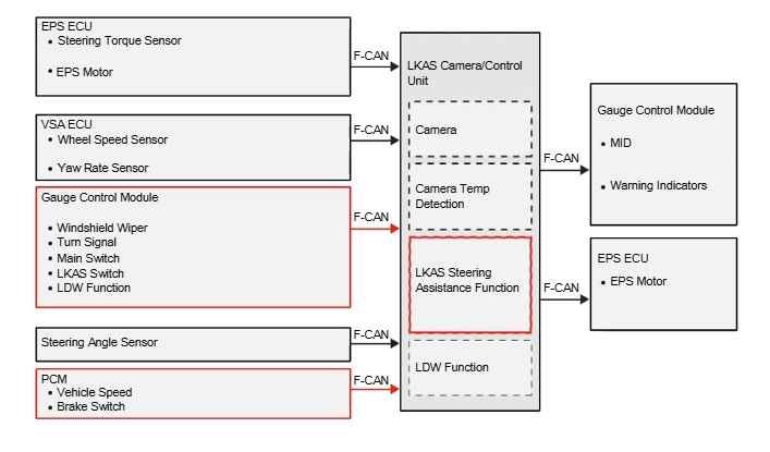
KAS Operation Part 3
The LKAS Camera/Control Unit processes this information and sends commands to the EPS ECU for calculated steering output.
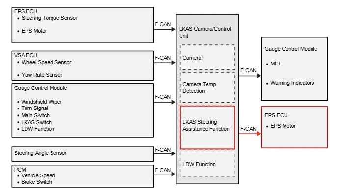
LDW Operation Part 1
To control the Lane Departure Warning function, the LKAS Camera/Control Unit receives information from its integrated camera, VSA Control Module, PCM and Gauge Control Module.
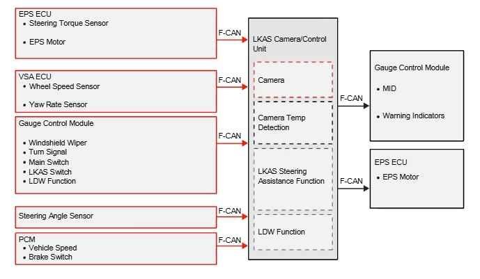
LDW Operation Part 2
The LKAS Camera/Control Unit sends commands to the Gauge Control Module to display LDW status and issue warnings.
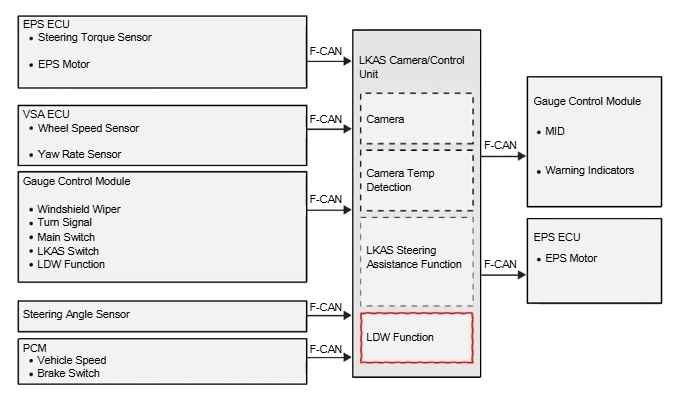
LDW Operation Part 3
The LKAS Camera/Control Unit contains all Lane Departure Warning logic within the article.
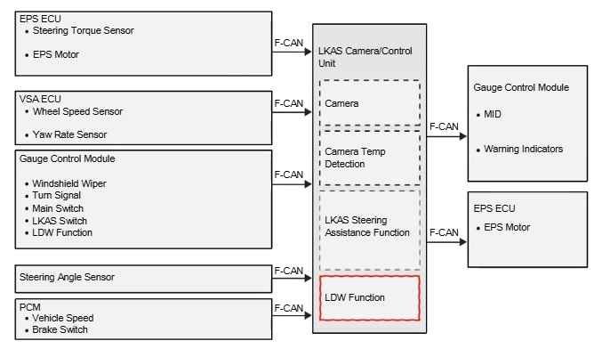
LDW Operation Part 4
The LDW switch activates the LDW function.
The gauge control module displays LDW system messages in the MID.
The camera identifies lane markings.
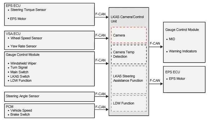
LDW Operation Part 5
Vehicle speed and brake switch information is received from the PCM.
Wheel speeds and yaw rate information are received from the VSA ECU.
Lane position information is received from the camera.
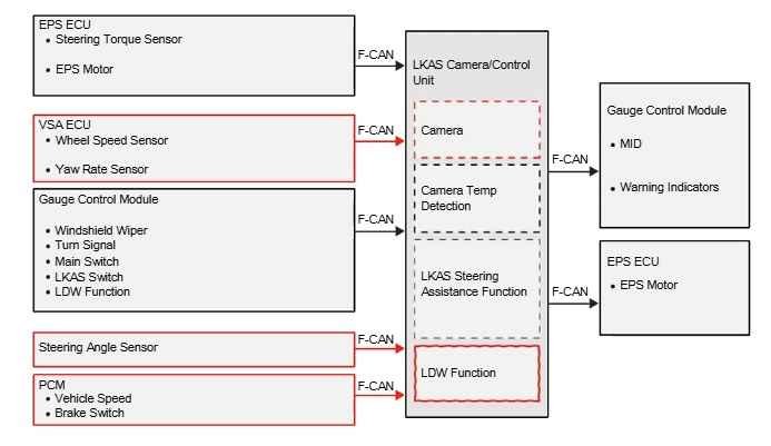
LDW Operation Part 6
The LKAS Camera/Control Unit processes this information and sends commands to the gauge control module for status display and warning outputs.
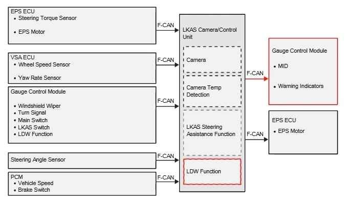
Control Malfunction
In the event of LKAS or LDW
malfunction, the LKAS Camera/Control Unit sends commands to the gauge control module to display malfunction status.
DTC information is stored within the LKAS Camera/Control Unit and is accessed using a scan tool.
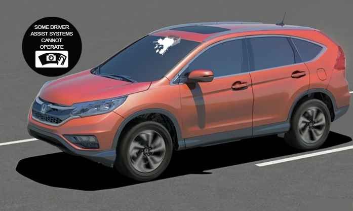
Service Considerations: a Blocked
If the camera view becomes blocked, the system will issue a warning in the MID.
Cleaning or removing the obstruction will enable the system to become operational again.
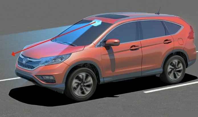
Service Considerations: Carema
Proper alignment of the LKAS camera is critical for the proper operation of the Lane Keep Assist System.
The camera needs to be aimed any time the windshield or the LKAS Unit is replaced or after the vehicle has had significant collision repairs.
Two different aiming methods can be used:
One is Target Alignment Calibration, The other is Service Point Calibration.
Service Considerations: Carema Aiming
Target Alignment Calibration is a static alignment using a series of black and white targets to calibrate the LKAS camera.
Service Point Calibration is a dynamic alignment that requires the vehicle to be driven within certain parameters to be completed.
For specific procedures, refer to the Service Manual information.

Service Considerations: System Malfunctiions
The Lane Keeping Assist System sets DTCs when system failures occur, including LDW DTC’s.
In addition, VSA DTCs will cause the LDW warning indicator lamp to turn on, and will cause the Lane Keeping Assist System to become inoperative.
In these cases, troubleshoot the VSA system before troubleshooting the Lane Keeping Assist System.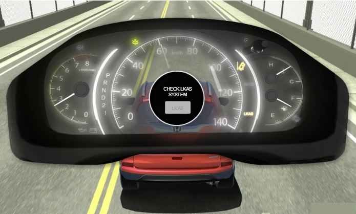
Post Comment